Photoelectrics Through-beam, Relay Output, Battery Powered Type PD180CBT30Q/MU • Industrial doors and gates • Range 15 m or 30 m • Modulated, infrared light • Supply voltage: 12 to 24 VAC/DC (receiver) • Supply voltage: 2 x 3.6 VDC Lithium batteries (emitter) • SPDT relay output • SPDT relay low battery • LED for output indication • Protection: reverse polarity, transients • Connection, terminal block • Emitter mute Product Description Ordering Key PD180CBT30Q/MU Housing style Housing size Housing material Battery operated Detection principle Sensing distance Output type Output configuration Mute function Type Selection Ordering no. Ordering no. Receiver 180 x 51 x 49 mm PD180CBT30MU PD180CBT30Q Specifications Emitter Rated operatibg dist (Sn) Protection Mute input Rated operational volt. (Ue) Light source Battery lifetime Light type Optical angle Supply current
* Without aperture the distance is increased by 30 %
Specifications are subject to change without notice (27.07.2009)
Specifications Receiver Rated operating dist. (Sn) Ambient light Optical angle Blind zone Protection Temperature drift Operating frequency (f) Hysteresis (H) Response time Rated operational volt. (Ue) Power ON delay (tv ) Ripple (Urrp) Indication function Output current (both outputs) No load supply current (Io)
*** With aperture removed the distance and angle will be increased, and the
General Specifications Environment Rated insulation voltage Housing material Connection Temperature Vibration CE-marking Approval Lens adjustment Operation Description
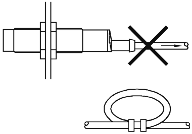
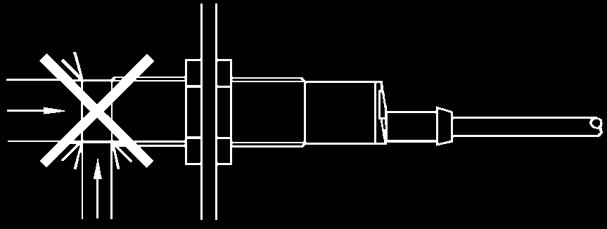
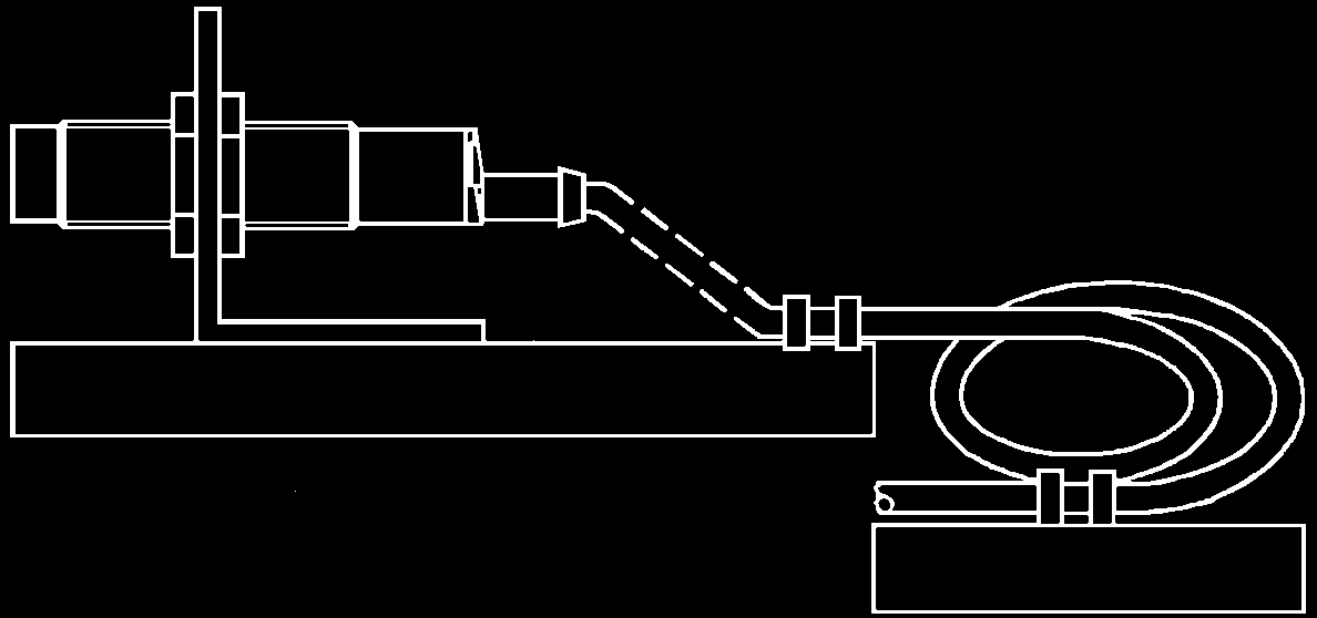
• The sensor shall be mounted with the draining hole facing down. • The cable must be mounted pointing downwards to avoid water entering the sensor (See Dimensions). • This product can only be used to detect direct interruption between Tx and Rx; it must not be reflected• The sensors must be mounted on a hard vibration-free surface• In order to obtain an “ESPE type 2” safety device, the sensors must be connected to a control system fittet with “Photo
test” or similar sensor verification function. Operation Diagram
Specifications are subject to change without notice (27.07.2009)
Dimensions Detection Diagram Sensing range (m) Excess Gain in a G s s e c x E Distance (m) Wiring Diagram Delivery Contents • PD180 emitter or receiver (separate box) • Installation instruction in emitter box Receiver • Packaging: Cardboard box • 2 x 3 screws for raw plugs ø2.9 x 25 DIN 7981C 12 to 24 VAC/DC • 2 x 3 raw plugs for 8 mm hole • 2 x 1 Strain releif • 2 x 2 Screws for strain releif M3 x 12 mm Mute input • 2 x 1 Cable gland Installation Hints To avoid interference from inductive voltage/current peaks, separate the prox. switch pow-er cables from any other power cables, e.g. motor, contactor or solenoid cables
Specifications are subject to change without notice (27.07.2009)
Acne Therapy Supplement to the Acne Drug Comparison Chart March 2007 The RxFiles Academic Detailing Program www.RxFiles.ca Key Messages, Tips and Pearls ACNE Therapy: Pharmacological Overview • Benzoyl Peroxide ( BP ) is used as 1st line monotherapy for mild- 1) Acne drug therapies require consistent use for several weeks before optimal results are seen. o B
Ophthalmic Contract Visit Form To be completed by the PCT (References in brackets in bold italics are references to clauses of the model mandatory or additional services as appropriate) Voluntary information is highlighted with grey background shading Section A – All Contracts 1. Practice Details 1.1 Practice Name (66.3) 1.2 Contractor Name (If different)

 Photoelectrics

 Dimensions